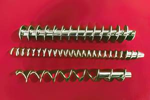
EXTRUSION: Are Grooved-Feed Extruders Right for You?
In specific circumstances, this design can increase output and reduce melt temperature. But grooved feed throats are not for every application.
There are basically two types of single-screw extruders, distinguishable primarily by their feed-throat design. Most single-screw extruders have smooth-bore feed throats—basically a smooth pipe surrounding the rotating screw.
Extruders with smooth-bore feed throats are affected a number of ways by the resistance or “head” pressure against which the screw is rotating. As the head pressure increases, a reverse flow (or pressure flow) develops in the screw channels that subtracts from the output (or drag flow) while increasing the melt temperature (because the material is essentially being recirculated back into the screw). This can cause significant problems in extrusion processes that have inherently high head-pressure characteristics resulting from a narrow die gap, such as in blown film, extrusion coating, and thin-wall tubing.
With a smooth-bore feed throat, solids transport of material with the rotating screw is highly dependent on the friction of the polymer particles against the barrel wall. Depending on the polymer and the temperatures, the feed efficiency is typically 15% to 30% based on the channel volume because of “slip” of the polymer particles on the feed-throat wall.
The second type of feed throat has grooves or interruptions machined into the feed-throat wall. Extruders with grooved feed throats resist rotation of the solid polymer particles against the feed-throat wall. This can increase conveying efficiency multiple times. Additionally, because the polymer is much more rapidly compacted into a solid and cannot slip on the feed-throat wall, the screw flights act as a spiral wedge multiplying the pressure development.
As this spiral block of polymer moves down the feed throat, it becomes highly pressurized compared with what occurs in a smooth-bore extruder. In the absence of any melting, which reduces the pressure development, the pressure tends to rise exponentially with groove length. Groove lengths are usually 4D or less because of the exponential rise in pressure and the difficulty in preventing melting from occurring over longer lengths.
Pressures exceeding 12,000 psi have been achieved at the end of the grooved section, so care must be exercised in design to prevent over-pressurization of the barrel. That can be done modifying the design of the grooves themselves, or by designing a decompression section in the screw. This pressure offsets, and in many cases can exceed, the pressure at the discharge. The grooved feed throat is intensively cooled so the material won’t prematurely melt and hinder pressure development.
Since the barrel is essentially a pipe, the pressure from the grooved feed throat transfers through the barrel, counteracting the discharge-pressure resistance. If the feed-throat pressure development exceeds the discharge pressure, the output will exceed the drag flow, resulting in further throughput gains.
To illustrate, I recently observed a test on a 90-mm extruder processing fractional-melt HDPE at a plant I visited. Using a barrier screw design, the output of the grooved-feed-throat extruder was 563 lb/hr, with a melt temperature of 418 F at a screw speed of 95 rpm. Head pressure was 6200 psi. With an essentially identical 3.5-in. smooth-feed-throat extruder having a similarly designed screw, the output was 445 lb/hr at the same screw speed and a slightly lower head pressure. The melt temperature was 432 F. That’s an 26.5% increase in output and a 27° F drop in melt temperature.
That said, before deciding to move to a grooved feed throat, weigh the advantages against the disadvantages for your process.
The advantages of grooved feed throats:
• Reduction or elimination of the effect of high head pressure, resulting in higher output.
• Reduction in melt temperature at same output.
• Stabilized output.
• Not very sensitive to barrel temperatures.
The disadvantages of grooved-feed throats:
• Proportionally more drive power required.
• Performance very sensitive to particle characteristics.
• Generally not suitable for most regrind due to plugging of the grooves.
• Does not work on “soft” polymers like many TPEs due to plugging of the grooves.
• Not as good for compounding additives without extensive mixing sections due to higher specific output.
• Not generally suitable for powdered polymers or additives.
• Can have accelerated screw/barrel wear without accurate balanced design due to higher pressures in feed section.
• Can be unstable with “hard” polymers such as polycarbonate.
• Requires higher volume of cold water for cooling.
• Requires a special screw design, unlike those used for smooth bore extruders.
Grooved-feed technology was developed in Germany in the early 1960s and has been more widely used in Europe than in other parts of the world. However, this design is the standard everywhere for much of HDPE pipe and HMW-HDPE blown film production.
In the late 1960s, Dr. Georg Menges and a group of associates at the IKV at Aachen University published guidelines on using grooved feed throats. While they mostly still apply, new designs have emerged, particularly at the point where the polymer enters the screw, along with varying the shapes of the grooves to accommodate a broader range of polymer particles. Now, grooved-feed designs are more commonplace. Many barrier blown film lines, for example, are equipped entirely with grooved-feed extruders.
Meantime, there also have been many developments in feed-throat “surface improvements.” Though not to be confused with traditional grooved feed throats, these surfaces aim to improve friction at the feed-throat wall by using shallow grooves of various designs. They’ve been shown to significantly improve output with polymers having low feed efficiency, and are effective when processing regrind and fillers. However, where screw design is concerned, they follow the principles of smooth-bore feed throats.
Bottom line: Grooved feed throats have their pros and cons. As a processor, weigh the promise of improved output and lower melt temperature against the disadvantages. Consider them only for situations where they are beneficial overall to the process. Don’t think of them as general-purpose extruders.
Related Content
What to Know About Your Materials When Choosing a Feeder
Feeder performance is crucial to operating extrusion and compounding lines. And consistent, reliable feeding depends in large part on selecting a feeder compatible with the materials and additives you intend to process. Follow these tips to analyze your feeder requirements.
Read MoreMedical Tubing: Use Simulation to Troubleshoot, Optimize Processing & Dies
Extrusion simulations can be useful in anticipating issues and running “what-if” scenarios to size extruders and design dies for extrusion projects. It should be used at early stages of any project to avoid trial and error and remaking tooling.
Read MoreWhere and How to Vent Injection Molds: Part 3
Questioning several “rules of thumb” about venting injection molds.
Read MoreInjection Molding: Focus on these Seven Areas to Set a Preventive Maintenance Schedule
Performing fundamental maintenance inspections frequently assures press longevity and process stability. Here’s a checklist to help you stay on top of seven key systems.
Read MoreRead Next
Making the Circular Economy a Reality
Driven by brand owner demands and new worldwide legislation, the entire supply chain is working toward the shift to circularity, with some evidence the circular economy has already begun.
Read MoreLead the Conversation, Change the Conversation
Coverage of single-use plastics can be both misleading and demoralizing. Here are 10 tips for changing the perception of the plastics industry at your company and in your community.
Read More.jpg;width=70;height=70;mode=crop)


