Updated Software Reduces Die Design Iterations
New software said to reduce the number of fine-tuning iterations and die development time by at least 50%.

Virtual fine-tuning and optimization of extrusion dies using ’s updated polyXtrue and optiXtrue software reduces the number of fine-tuning iterations and die development time by at least 50%. The company says current customers report a 60% to 70% reduction in the number fine-tuning iterations once they introduced flow analysis by polyXtrue as an integral part of their extrusion die design process.
The software module for the level-set method for simulation of the flow in multilayer coextrusion dies has been completely rewritten to largely improve the accuracy of predicted layer structure. For most coextrusion dies, both coextrusion simulation techniques in polyXtrue (level-set method and mesh partitioning techniques) now give almost the same layer structure in the final product. Robustness of the level-set algorithm for simulating the flow in different types of coextrusion dies has also been improved in the new version of the software.


The algorithm for enforcing the symmetry condition in post-die extrudate distortion has been updated to accurately satisfy symmetry, including the change in extrudate shape due to nonuniform exit velocity as well as due to cooling shrinkage.
Besides plotting the results along the cut planes parallel to XY, YZ and XZ planes, in the new version of polyXtrue results can also be plotted on cut planes along other cut-plane orientations.
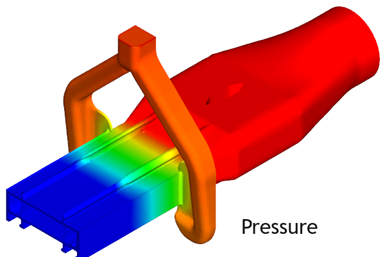
Pressure in a window profile die predicted by polyXtrue. Image Credits: Plastics Flow LLC.
The ability to calculate the flow rate through a quadrilateral or an annulus on a cut plane has also been implemented for noncoordinate cut planes.
What’s more, new materials have been added to the polyXtrue material database. The material database in the new version has more than twice the number of materials available in the last release. The newly added materials include the structural analysis parameters required for an accurate prediction of extrudate shrinkage. These structural analysis parameters have also been added for many of the previously existing materials in the database.
The graphical user interface (GUI) of the software has also been updated with new features to make the software more effective and even more user friendly. These include:
- A Command Bar with shortcut buttons for common or useful features has been added to the User Interface.
- The default save location can be set according to “File Extension” or “By Last Save.”
- The ability to move a company's material database to a shared network drive has been added. This shared material database feature allows every user in a company to access all material files generated by anyone in the company, and ensures everyone is using the same version of the material files.
- The ability to shift and rotate a calibrator profile has been added. This ability enables the user to adjust the calibrator location and orientation if the calibrator DXF file does not line up properly with the die exit.
- The ability to generate a locally refined mesh and boundary layer mesh around a Vertex has been added.
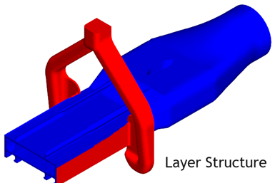
Layer structure in a window profile die predicted by polyXtrue.
- A new exit “Curved Faces” feature has been added to the local meshing dialog. This feature adds the die wall faces adjacent to smaller fillets along the die exit to the local mesh table and ensures the fillet curves are captured accurately in the predicted extrudate profile.
- Option to hide “Post-Die Results” has been added to the Display Controls panel. This feature enables a close examination of the die results near the exit without interference from the post-die results in the extrudate.
- The “Visualize Die Results” and “Visualize Interface Results” dialogs have been merged into one dialog to facilitate switching back and forth.
- A “Cross flow” option has been added to the “Velocity” results to view the velocity perpendicular to the flow at the exit.
- Streamline generation has been separated from “Results” plotting. This enables the user to plot results without waiting for streamline generation to complete.
- Point Thickness, the thickness calculated at points on the die or extrudate by holding down the shift key while clicking the right mouse button, can be saved to a CSV file and imported into a spreadsheet for further analysis.
The Point Thickness feature now also reports the thickness of each polymer layer at the clicked point in a coextrusion simulation. Layer thickness is shown in the polyXtrue Status Window.

Related Content

Why Are There No 'Universal' Screws for All Polymers?
There’s a simple answer: Because all plastics are not the same.
Read More
NPE2024 Wrap-Up: Sustainability Dominates Show Floor News
Across all process types, sustainability was a big theme at NPE2024. But there was plenty to see in automation and artificial intelligence as well.
Read More
Roll Cooling: Understand the Three Heat-Transfer Processes
Designing cooling rolls is complex, tedious and requires a lot of inputs. Getting it wrong may have a dramatic impact on productivity.
Read More
How Polymer Melts in Single-Screw Extruders
Understanding how polymer melts in a single-screw extruder could help you optimize your screw design to eliminate defect-causing solid polymer fragments.
Read MoreRead Next

Beyond Prototypes: 8 Ways the Plastics Industry Is Using 3D Printing
Plastics processors are finding applications for 3D printing around the plant and across the supply chain. Here are 8 examples to look for at NPE2024.
Read More
See Recyclers Close the Loop on Trade Show Production Scrap at NPE2024
A collaboration between show organizer PLASTICS, recycler CPR and size reduction experts WEIMA and Conair recovered and recycled all production scrap at NPE2024.
Read More