Mechanical Limit Switches Communicate Mold Components’ Positions
Hasco says its new mechanical Z1430/... limit switches monitor the position of moving components like ejector pins and core pullers in injection molding tools.


Hasco says its new Z1430/... mechanical limit switches track the positions of moving components in injection molding and punching tools. Using these, molders can know the final positions of ejector assemblies, as well as other moving mold components like core pullers and stripper plates.
The limit switches, which can be used at a maximum mold temperature of 140C, can be adjusted via Hasco’s excenter Z14300/... distance block, with a proven actuation range of 0.8 mm. The switches operate as a normal open contact so that an electronic contact is closed when the switch is pressed.
An internal circuit protects the limit switches from damage if the supply voltage connections are set up incorrectly, preventing the sending of an undesired signal. The testing and adjustment of the limit switch is carried out by the battery-operated testing device Z 141/3.
The limit switches are connected via three-pin connecting cables Z14301/… - Z14304/... with straight or 90-degree angled connectors, both to the mold control and, if necessary, to the testing device. Available in vertical and horizontal design, the switch can be outfitted as needed with a male or female connector for the connecting cable.
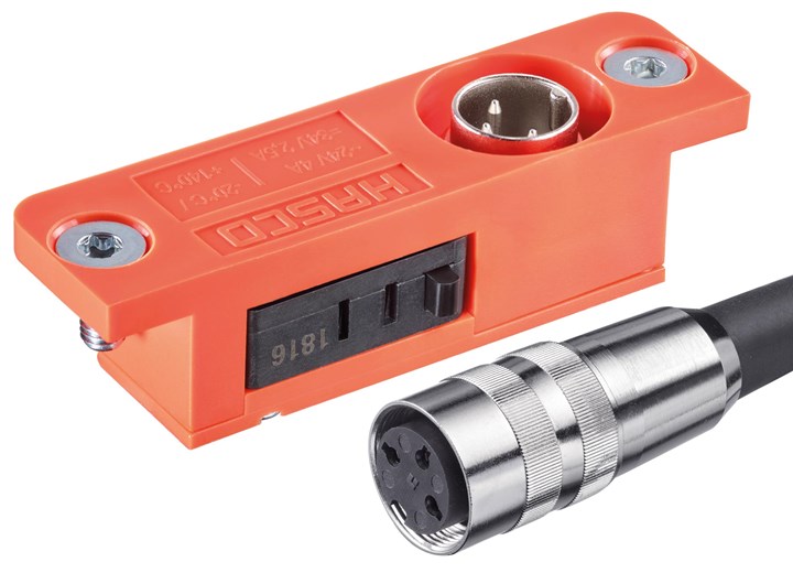
Hasco’s new mechanical limit switches help track the position of moving components in an injection mold.
Photo Credit: Hasco
Related Content
-
Hot Runners: How to Maintain Heaters, Thermocouples, and Controls
I conclude this three-part examination of real-world problems and solutions involving hot runners by focusing on heaters, thermocouples, and controls. Part 3 of 3.
-
Hot Runners: Truths. Myths, Overlooked Areas: Part 2
Here’s a view from the trenches of a tooling manager who, over 30 years, has experienced the joys and pains of using virtually every type of hot runner on the market. Part 2.
-
Three Key Decisions for an Optimal Ejection System
When determining the best ejection option for a tool, molders must consider the ejector’s surface area, location and style.