EXTRUSION: Feedblock Fine-Tunes Layers, Balances Velocities
Device is adjustable in-line and is available with larger than usual channel widths to reduce shear stress and interfacial instability.
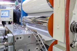
A next-generation coextrusion feedblock from Nordson Corp. reportedly enables processors of film, sheet, and coatings to fine-tune individual layers as well as accommodate changes in layer ratio, and to adjust the tuning system without removing the feedblock from the production line. Nordson will introduce the patent-pending technology at K 2016, along with the availability of feedblocks with wider than standard flow channels that are said to reduce shear stress and enhance end-product quality and consistency.
The EDI Ultraflow V-T feedblock has separate devices for fine-tuning layer stability and thickness uniformity, and both are capable of being adjusted without stopping production. As in the widely used Ultraflow V feedblock, one of these devices is a pair of “combining planes” (located where the outer-layer melt streams join the core layer in the central flow channel) that fine-tune the overall structure by adjusting the gaps at the point of layer combination. What is new is a pair of “profiling actuators” (located opposite the combining planes) within which are mounted interchangeable “profile bars” that fine-tune the thickness uniformity of the individual layers (see schematic). For coextrusion of more than three layers, additional tuning devices are placed farther downstream, where more melt streams join the central structure.
“Because the profiling actuators are large in diameter, they accommodate wider profile bars and enable them to be positioned either close to or farther from the layer combining point,” says Sam G. Iuliano, 大象传媒 development manager for polymer dies. “This provides more area for tuning layer thickness uniformity and thus makes possible more accurate and effective tuning. In addition, changing the position of the profile bars dramatically changes the result, allowing for significant process refinements to be made on-the-fly.”
The positioning of the profile bars with respect to the combining point is adjusted by rotating the profiling actuators. This is accomplished by turning nuts on the outside of the feedblock in accordance with a position indicator and does not entail stopping production.
The profile bars are available with various surface configurations, including a standard bar with a uniform raised surface and others designed to correct such issues as heavy end flow, heavy center flow, or “M” or “W” patterns. The bars are installed in dovetail grooves in the surface of the profiling actuators. A cover plate in the feedblock provides access for replacing one set of bars with another.
“Adjusting the profiling actuators in the Ultraflow V-T feedblock makes it possible to influence the distribution of a particular layer,” states Iuliano. “If further adjustment is necessary, one can replace the profile bars by briefly stopping production, without having to remove the feedblock from the extrusion line.”
Nordson will specify a feedblock whose flow channel differs in size from the standard 4 in. (100 mm), with widths available from 2 in. (50 mm) up to 7 in. (180 mm) depending on the width of the product to be extruded. Larger-volume feedblock channels reduce the shear stress levels at the layer interfaces and a wider feedblock channel contributes to a more consistently on-specification product. In the case of a 100-in. (2,540-mm) die, for example, the spreading ratio is 25:1 for a 4-in. feedblock channel but only about 14:1 for a 7-in. channel.
“As in the Ultraflow V feedblock, the combining planes in the new Ultraflow V-T system combine polymers in a parallel-path manner, achieving optimal layer ratio stability throughout the structure,” Iuliano explains. “Their ability to be adjusted ‘on the fly’ increases uptime and allows for greater end-product versatility.”
The Ultraflow V-T feedblock is available with Nordson’s optional selector spool that allows the layer sequence to be pre-arranged upstream of the combining point, without removing the feedblock from the production line.
Related Content
Roll Cooling: Understand the Three Heat-Transfer Processes
Designing cooling rolls is complex, tedious and requires a lot of inputs. Getting it wrong may have a dramatic impact on productivity.
Read MoreWhy Are There No 'Universal' Screws for All Polymers?
There’s a simple answer: Because all plastics are not the same.
Read MoreUnderstanding Melting in Single-Screw Extruders
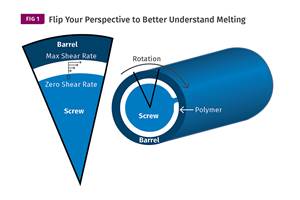
You can better visualize the melting process by “flipping” the observation point so the barrel appears to be turning clockwise around a stationary screw.
Read MoreHow To Identify Resin Degradation in Single-Screw Extruders
Degradation can occur in many single-screw extrusion operations, and typically occurs due to minor design flaws in the screw. Here is how to track it down.
Read MoreRead Next
Lead the Conversation, Change the Conversation
Coverage of single-use plastics can be both misleading and demoralizing. Here are 10 tips for changing the perception of the plastics industry at your company and in your community.
Read MoreBeyond Prototypes: 8 Ways the Plastics Industry Is Using 3D Printing
Plastics processors are finding applications for 3D printing around the plant and across the supply chain. Here are 8 examples to look for at NPE2024.
Read MoreSee Recyclers Close the Loop on Trade Show Production Scrap at NPE2024
A collaboration between show organizer PLASTICS, recycler CPR and size reduction experts WEIMA and Conair recovered and recycled all production scrap at NPE2024.
Read More


