Save Time, Money: Use a Mold-Design Checklist
Here are 15 examples of common molding issues that occur during an initial mold trial. Many of them could be avoided or corrected with a proactive checklist.


Injection molders quote or estimate a job based on six primary factors: part weight, material cost, machine size, cycle time, labor requirements and packaging. The material and packaging costs are relatively easy to obtain from suppliers, which makes them fixed values—not estimates. Thanks to solid modeling software programs, part weight is also a fixed value, based on the models volume and the density of the material.
That leaves three variables, or estimates made by the person quoting the job: cycle time, machine size and labor requirements. These three estimates typically determine if you are going to make money or lose your shirt. More often than not, the mold design can control all three of these variables, because the estimator doesn’t base his or her costs on having an issue with the mold. He, or she, base them on the mold performing as it should—in the correct machine, at the anticipated cycle time, and with the expected number of operators required.


Cycle time, machine size and labor requirements are the big three cost variables—that can be controlled by the mold design.
Smart moldmakers use a mold-design checklist to help ensure they don’t overlook anything. Most checklists that I have seen include details such as pry slots, insulator plates, steel types, safety straps, interlocks, etc. They all relate to the mold construction, but not the molding process.
The automotive and medical industries (as well as the military) insist on using all sorts of comprehensive checklists, with acronyms such as APQP (Advanced Product Quality Planning), PPAP (Production Part Approval Process), FMEA (Failure Mode and Effects Analysis), DOE (Design of Experiments), IQ/OQ/PQ (Installation Qualification/Operational Qualification/Process Qualification) and Mil Spec (Military Specification). Most of these checklists address the function of the part, or the repeatability of the mold and machine to make the part.
Very few checklists are geared towards preventing mold-design problems that arise at the initial mold sampling. I’m talking about problems that cause the cycle time to be extended, the machine size to be larger, the labor requirements to be increased—or even prevent the mold from running in full auto mode. They don’t include any “what if” questions. What can be done if this or that happens during the initial mold trial? I call this a “Proactive Mold Design Checklist.” Merriam-Webster aptly defines proactive as “acting in anticipation of future problems, needs, or changes”.
In this column I’ll give 15 examples of common molding issues that occur during an initial mold trial. Many of them are avoidable or correctable with a proactive checklist. Each example will list a question or questions that relate to the problem, which you might want to add to your checklist.
Common Molding Issues
1. A mold is built and it’s time to sample it. The machine tonnage, tiebar spacing and shot size were all taken into account during the mold design phase. The processor starts to dial in the machine settings. The first thing he encounters is the 4-in.-tall part will not eject off the core because the machine only has 31/2 in. of ejector stroke. Oops!
• Do we have the intended molding machine’s specification?
• Is the machine’s ejector stroke long enough?
If not, can outboard puller bars, or some other mechanical method be
added?
2. The mold has an eight-drop hot-runner system with 12 heat zones. The processor has no idea what zone controls which component. He turns the controller on. The zones that come up to heat slowly are for the manifold. The zones that come up to heat quickly are for the cavities.
• Is a wiring schematic needed for the molder?
If so, do the zone numbers correspond with the cavity numbers?
3. The mold has a stripper-plate ejection system. When the processor starts to determine the transfer position by making progressively larger short shots, the parts don’t eject because the stripper plate is not pushing against any plastic yet.
• Was the shot volume provided to the molder in cubic inches, or the shot weight in grams? The processor can do the math based on the barrel diameter and the volume, or he can simply take an air-shot and weigh it.
4 . The cavities are out of balance. Some of them fill out way before the others, but the processor can’t identify which cavities are the short ones.
• Is the cavity identification engraved near the gate, and not at the end of fill?
5. The four inside cavities fill first and the four outboard cavities are short.
• Is each runner branch feeding the parts long enough to be effective when attempting to balance the cavities after the initial trial? Do not attempt to balance a mold by modifying the gate sizes. Gate widths and depths should be identical to all cavities. Otherwise, you will get packing and warping issues. You will also get an extended cycle time due to a variation in gate-freeze time. Balance the cavities by changing individual runner diameters. Long runner branches are easier to balance individual cavities (see Figs. 1 and 2).
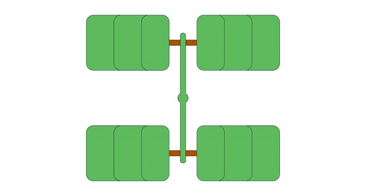
FIG 1 Difficult-to-balance cavities
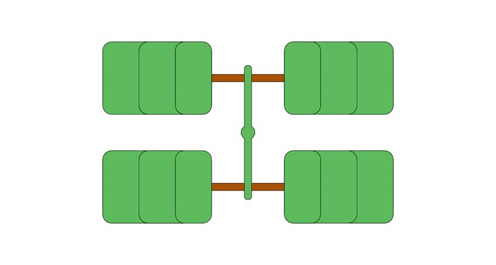
FIG 2 Easier-to-balance cavities (due to long runner branches).
6. A mold-filling analysis was performed prior to designing the mold and the results said the part requires 100 tons of clamp pressure. The mold is sampled in a larger, 150-ton machine, but the processor still can’t pack out the sink without getting flash.
• Should the parting line be relieved for more clamp force around the cavity?
• Should the center support pillar(s) be pre-loaded?
• Are the clamp plates thick enough to counteract platen wear?
• Can the sprue, runner and gate sizes be increased if necessary to reduce the injection pressure?
• Should a flash trap be added around the perimeter of the runner?
• Can a second gate be added to the part if necessary?
7. The mold-filling analysis estimated the cycle time to be 30 sec. That is what the estimator used when quoting the job. The best cycle the processor could achieve in order to make a good part was 40 sec due to inadequate cooling in various areas.
- ​​Are all of the molding areas adequately cooled. This includes everything from the sprue bushing, all the way to the end of fill.
• Should any area of the part be cored out?
• Should the core or any other mold component be made of beryllium copper, aluminum, or other thermally conductive material, especially for molds with short cycle times, thick wall sections, and places that are difficult to add a cooling channel?
•â€‹â€‹â€‹â€‹â€‹â€‹â€‹ Would conformal cooling be beneficial?
•â€‹â€‹â€‹â€‹â€‹â€‹â€‹ Would a post molding cooling fixture be beneficial?
8. The part is sub-gated into either the ejection side or the injection side of the mold. Upon mold opening, or upon ejection, the sub-gate breaks off the runner and stays in the mold, which then blocks the cavity on the next shot.
•â€‹â€‹â€‹â€‹â€‹â€‹â€‹ Is there sufficient land length on the ejector pin, or puller pin next to the gate, so that it can be shortened, to form a longer boss connected to the runner?
•â€‹â€‹â€‹â€‹â€‹â€‹â€‹ Can a stiffening rib or gusset be added in case there is an issue with the gate?
•â€‹â€‹â€‹â€‹â€‹â€‹â€‹ If the ejector pin, or puller pin next to the gate, ends up being too close or too far away, is there room to add another pin in a different location?
The location of the ejector pin or gate puller frequently doesn’t allow the runner to flex, or it allows the runner to flex too much. That is often the reason why a sub-gate will break off.
9. The parts have a fairly thin wall section and the material is unfilled nylon 66. The injection velocity is pretty fast, so that the parts fill before the small gates freeze off. The parts have a lot of burn marks, but if the processor slows down the injection speed, the cavities won’t fill.
•â€‹â€‹â€‹â€‹â€‹â€‹â€‹ Should a perimeter vent be added?
•â€‹â€‹â€‹â€‹â€‹â€‹â€‹ Should a runner vent near the gate be added?
•â€‹â€‹â€‹â€‹â€‹â€‹â€‹ Can any rib, boss or other “dead zone” be vented?
•â€‹â€‹â€‹â€‹â€‹â€‹â€‹ Should a vent pin or porous metal insert be added?
•â€‹â€‹â€‹â€‹â€‹â€‹â€‹ Can the land lengths of the vents be shortened if necessary?
•â€‹â€‹â€‹â€‹â€‹â€‹â€‹ Can a flow leader be added if the part is difficult to fill?
10. When sufficient pack pressure is used to eliminate the sink marks, the part wants to stick in the cavity. When mold release is sprayed in the cavity, the sticking goes away for a few shots.
•â€‹â€‹â€‹â€‹â€‹â€‹â€‹ Is there sufficient draft on the outside of the part?
•â€‹â€‹â€‹â€‹â€‹â€‹â€‹ Can undercuts or a rough texture be added to the core?
•â€‹â€‹â€‹â€‹â€‹â€‹â€‹ Should a vent or air poppet be added to the cavity?
11. When sufficient pack pressure is used to eliminate the sink marks, the ejector pins try to push through and leave circular stress marks on the part.
•â€‹â€‹â€‹â€‹â€‹â€‹â€‹ Can more or larger ejector pins be added if there is a “pin-push” issue?
•â€‹â€‹â€‹â€‹â€‹â€‹â€‹ Has a draw polish been specified to help with release?
•â€‹â€‹â€‹â€‹â€‹â€‹â€‹ Is there sufficient draft on the inside of the part?
•â€‹â€‹â€‹â€‹â€‹â€‹â€‹ Should a lubricous plating or coating be added to the core?
12. The parts have deep, thin ribs. At first, the ejector pins push right through ribs. The parts eject, but the ribs break off and stay in the core. The processor’s hands are badly bruised from trying to remove the ribs with a propane torch and a straightened out band clamp. After several attempts and a lot of frustration, the small ejector pins under the ribs simply buckle and break. In addition to the checklist questions above:
•â€‹â€‹â€‹â€‹â€‹â€‹â€‹ Should bosses be added to any ribs or deep impressions?
•â€‹â€‹â€‹â€‹â€‹â€‹â€‹ Should blade ejection be added to ribs for more ejection contact area?
•â€‹â€‹â€‹â€‹â€‹â€‹â€‹ Should a “floating” insert be added to release any ribs or deep impressions?
13. The mold has two opposing lifters, which form undercuts on the part. When the ejector plate advances forward, the part releases from one of the lifters, and sticks like glue to the other. Multiple ejector pulses still don’t eject the part. It just goes back and forth for a ride.
•â€‹â€‹â€‹â€‹â€‹â€‹â€‹ Should a boss, rib or pointed ejector pin be added to keep the part centered during ejection?
•â€‹â€‹â€‹â€‹â€‹â€‹â€‹ Should a two-stage ejector system be added?
•â€‹â€‹â€‹â€‹â€‹â€‹â€‹ Can an air blast be added if there is an ejection issue?
14. The runner on a three-plate mold is a real problem. Sometimes it hangs up on the sucker pins. Sometimes it curls and won’t fall out of the mold. Sometimes it hangs up on the extended sprue bushing due to nozzle-tip drool.
•â€‹â€‹â€‹â€‹â€‹â€‹â€‹ Does the runner clear the range bolts, springs, interlocks, or other obstructions?
•â€‹â€‹â€‹â€‹â€‹â€‹â€‹ Should the body of the sucker pins enter the runner about 0.010 in. to prevent “hang-ups?
•â€‹â€‹â€‹â€‹â€‹â€‹â€‹ Should a thin stiffening rib be added to the runner to prevent it from curling?
•â€‹â€‹â€‹â€‹â€‹â€‹â€‹ Should an air- or spring-actuated poppet with a long throw be added to push the runner off the floating X-1 plate?
15. The job was quoted using one-half an operator. In other words, one operator being able to attend to two machines. Therefore, the mold must run fully automatic and the operator must have sufficient time to perform such operations as degate the runner, apply a part label, put the part in a polybag, neatly pack the parts in a box, and inspect the part quality. Trimming flash is never taken into account when quoting a job. All of this leads to a few more checklist questions.
•â€‹â€‹â€‹â€‹â€‹â€‹â€‹ Can an operator degate the part cleanly and without too much difficulty?
•â€‹â€‹â€‹â€‹â€‹â€‹â€‹ Can the gate be recessed into the part?
•â€‹â€‹â€‹â€‹â€‹â€‹â€‹ Will a sub-gate, cashew gate or split pin gate help reduce the operator requirements?
•â€‹â€‹â€‹â€‹â€‹â€‹â€‹ Will the parts scuff or become damaged if they are ejected onto a chute or conveyor?
•â€‹â€‹â€‹â€‹â€‹â€‹â€‹ Will a robot or picker be used to remove the part?
If so, can the mold open up enough for the robot to fit inside?
Is the machine’s maximum daylight sufficient for robotic extraction?
Here’s a tip that the moldmaker, the molder, and the estimator should keep in mind: Molding machines have different hourly rates based on their clamp tonnage. The larger the machine, the higher the rate. In contrast, a molding machine operator has a fixed overhead rate, regardless of the molding machine size. If the molding machine has an hourly rate less than the operator’s burden rate, the primary concern should be the labor requirements. Conversely, if the molding machine has an hourly rate more than the operator’s burden rate, the primary concern should be the overall cycle time.
All molds have both commonalities and uniqueness.
There is an old saying in our industry: A moldmaker is only as good as his last mold. Molders understand that almost every mold is unique. They usually don’t get upset when an unforeseen problem arises. If the moldmaker says, “We considered the possibility of that happening during the design phase and we have an action plan in mind,” the molder is probably going to be impressed.
However, when a common mold problem occurs—one that is not unique and should have been foreseen and prevented—that is when the likelihood of a moldmaker getting another job starts to diminish. This is why the use of a thorough checklist can be financially invaluable. The checklist should be a “living” document, updated whenever an issue occurs. And they occur all the time.
About the Author Jim Fattori is a third-generation molder with more than 40 years of experience in engineering and project management for custom and captive molders. He is the founder of Injection Mold Consulting LLC in Pennsylvania. Contact: jim@injectionmoldconsulting.com;


Related Content

Fundamentals of Polyethylene – Part 6: PE Performance
Don’t assume you know everything there is to know about PE because it’s been around so long. Here is yet another example of how the performance of PE is influenced by molecular weight and density.
Read More
Three Key Decisions for an Optimal Ejection System
When determining the best ejection option for a tool, molders must consider the ejector’s surface area, location and style.
Read More
Part 2 Medical Tubing: Use Simulation to Troubleshoot, Optimize Processing & Dies
Simulation can determine whether a die has regions of low shear rate and shear stress on the metal surface where the polymer would ultimately degrade, and can help processors design dies better suited for their projects.
Read More
Medical Tubing: Use Simulation to Troubleshoot, Optimize Processing & Dies
Extrusion simulations can be useful in anticipating issues and running “what-if” scenarios to size extruders and design dies for extrusion projects. It should be used at early stages of any project to avoid trial and error and remaking tooling.
Read MoreRead Next

For PLASTICS' CEO Seaholm, NPE to Shine Light on Sustainability Successes
With advocacy, communication and sustainability as three main pillars, Seaholm leads a trade association to NPE that ‘is more active today than we have ever been.’
Read More
People 4.0 – How to Get Buy-In from Your Staff for Industry 4.0 Systems
Implementing a production monitoring system as the foundation of a ‘smart factory’ is about integrating people with new technology as much as it is about integrating machines and computers. Here are tips from a company that has gone through the process.
Read More