Overcome Typical Challenges in LSR Molding
Here’s a quick overview of basic mold and machine factors behind common LSR molding headaches and how to avoid them.
As the need for high-quality liquid silicone rubber (LSR) products has increased, so has the demand for machines and molds that support the production challenges faced each day. LSR molders often look for machines with all-electric drives, technology integration, and ability to run small parts consistently. Yet even with the repeatability afforded by high-quality machines and tooling, there are common day-to-day issues that every LSR run encounters.
MOLD HEATING AND VENTING
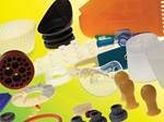
Several mold issues can bring LSR production to a halt. LSR applications often involve small parts that may weigh 0.017 g or less, which presents significant challenges.
Molds for such small parts must vent air and gases efficiently, as they can cause defects if not properly evacuated. In production, several defects that signal improper venting include short parts, knit lines, or flow lines. Short parts typically result from inadequate venting, improper process settings, or possibly an unbalanced cold deck.
The size and style of vents are best determined at the prototype stage to prevent delays and rework later on. The moldmaker will design the vent depth and width to balance gas evacuation efficiency with the need to control flashing of very low-viscosity silicones.
Some part geometries require more aggressive venting and therefore a compromise with flash, but in most cases the two competing goals can be met. The moldmaker can machine vents to ± 0.00001 in. to ensure they work properly and generally hold vent depths to around 0.000020 in. (20 millionths).
Some of the same defects—shorts, gas traps, and knit lines—can also result from mold heating problems. Inconsistent part dimensions could also be an indicator of improper heating. Common technical problems that cause uneven mold heating are improper sizing of the heaters relative to the size of the mold and improper heater spacing. Heaters must be spaced so that the cavity is heated uniformly, not just the backing plates.
AUTOMATION
Automation is another key concern for LSR molders. For example, the part must stay on the correct side of the machine every cycle so that automation can properly pull the part off. Since the parts are so small and the runs are often so large, consistency in automation is a key component. If parts do not stay in the same location every time, it makes the automation more complex and expensive. Some reasons that parts don’t stay on the same mold half from cycle to cycle include variations in the material, which can contribute to parts sticking on the wrong side. Mold coatings, engineering changes to the mold or part, and processing technique are all keys to keeping parts on the correct side.
Some LSR parts simply cannot be engineered in such a manner to ensure they will stay in the same place on every cycle, so more expensive automation is required. This is where building a prototype becomes so critical. It is easier to make adjustments on one cavity than on a 64-cavity mold. The prototype can be used to develop the automation strategy for a consistent process and cycle time. It also helps to work with mold and machine builders that have experience in a wide range of LSR molding solutions and that can provide reliable, high-quality automation.
The press must be equipped with the necessary EuroMap connection to allow for automation integration. As automation becomes ever more sophisticated, it is necessary for the press to be able to talk to the robot and other automation so that control is as seamless as possible and the safeties are maintained on the press.
MACHINE ISSUES
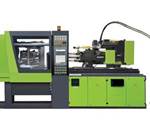
To run LSR effectively, the press needs an adequately sized vacuum pump that is capable of evacuating all the mold cavities quickly. If the vacuum pump is too small, this will increase cycle time while waiting for the cavities to be evacuated.
One important option on the press is provisions built into the machine controls to run a valve-gated cold deck. While it is possible to use a separate valve-gate controller, this adds another layer of equipment to the process, which is less desirable. Considering the variety of jobs a machine may be used for, new machines must be outfitted with the proper number of valve-gate controls. A good rule of thumb is to start with no fewer than eight valve-gate control solenoids.
Most cold decks are made to be divisible by eight. For a four-cavity mold, you can use four of the eight solenoids. In an eight-cavity mold, you can use one solenoid for one gate. This offers the best degree of control, but limited control can be achieved by operating multiple valve gates off the same solenoid. For example, with a 16-cavity mold, you can use the bank of eight solenoids to turn on eight pairs of valve gates at a time to give you limited control. A similar approach applies to operating 32 and 64 drops with eight solenoids. Clearly, it is desirable for the molder to have a clear idea of the parts and sizes of molds that will be run in the press so that the machine is developed originally with the optimum number of controls.
The press also needs to provide proper feedback for troubleshooting the process within the cycle parameters. The feedback mechanisms must include the capability of reading the mold heats and giving a visual display of all zones and how they are working.
Additional important feedback includes whether the machine is pulling adequate vacuum on the mold, as well as the injection speeds, hold times, and injection pressures from shot to shot. Adding mold-cavity sensors is an important advantage for gaining full control of the molding cycle.Molding small parts requires the machine and process to be able to control very small shot sizes accurately and repeatedly. The best machines for repeatability are ones in which all electrical motors/drives, software, and controls are developed from one company. Customers should look for machines that can produce LSR and small parts with tight tolerances and with high levels of motion control.
Related Content
What to Know About Your Materials When Choosing a Feeder
Feeder performance is crucial to operating extrusion and compounding lines. And consistent, reliable feeding depends in large part on selecting a feeder compatible with the materials and additives you intend to process. Follow these tips to analyze your feeder requirements.
Read MorePolyethylene Fundamentals – Part 4: Failed HDPE Case Study
Injection molders of small fuel tanks learned the hard way that a very small difference in density — 0.6% — could make a large difference in PE stress-crack resistance.
Read MoreHow to Configure Your Twin-Screw Barrel Layout
In twin-screw compounding, most engineers recognize the benefits of being able to configure screw elements. Here’s what you need to know about sequencing barrel sections.
Read MoreWhere and How to Vent Injection Molds: Part 3
Questioning several “rules of thumb” about venting injection molds.
Read MoreRead Next
Getting Into LSR: Part II--Chosing an Injection Machine
The criteria for selecting a liquid silicone rubber injection molding machine are very similar to selecting a machine for standard thermoplastic injection molding, with several key differences.
Read MoreClearly a Contender
LSR Vies for New Applications in Automotive, Lighting, Healthcare, and More.
Read MoreLSR Part III-- Choosing a Mixing/Metering System
Liquid silicone rubber (LSR ) is a two component reactive chemical with a viscous, paste-like consistency.
Read More